Gates and Boolean Basics
| Transistor | The microscopic switch which either allows or disallows the electrical impulse to pass through it. Older switches used: electromechanical and vacuum tube |
| Boolean Function | A boolean correspondence that has one or more input variables and yields a result that depends only on the values of these variables. F(A,B) = A'B + A'B' + AB |
| Logic Table (truth table) | Is constructed by considering all of the possible states that the logic variables could have. |
| Gates | Physical representation of some important and standard boolean functions: AND, OR, NOT, NAND, NOR, XOR, XNOR. Basic boolean components used to build larger (more meaningful) boolean circuits. |
| Boolean Circuit Equilvalence | The fact that two different set of boolean gates (circuits) can produce the same results. In fact, it is important to be able to transform a circuit using a variety of gates into a circuit using fewer gates or a different type of gate. |
Representation of data via switching
Our discussion of data representation in the last chapter has indicated that the simple symbols 0 and 1 can be used to represent a host of data: unsigned integers, signed integers, floating point numbers, typed alphabetic characters, computer instructions and even sounds and images.
It seems that we are saying that the computer is a device which has a special facility for manipulating lots of zeroes and ones. We have reminded ourselves, though, that computers do not really contain a myriad dance of zeroes and ones; instead, computers are filled with millions and millions of switches which are constantly being turned on and off in specific patterns, following some algorithm. The values 0/1 are then physically represented in the computer by the off/on position of the switches.
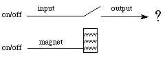
Switching Relays
Model:
Relay switches are built in two general ways: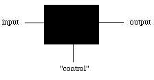
1. Normally open
Spring holds switch open |
|
2. Normally closed
Spring holds switch closed |
|
                Normally open             Normally closed

          Input:   off   on                 off     on
                -------------     	      ---------------
control:  off   |  off   off        off  |  off     on
control:  on    |  off   on         on   |  off     off
Transistors - "Solid state switches"
A switch with no moving parts:
Input is called "collector"
Output is called "emitter"
Control is called "base"
Transistors are also built in the "normally open" and "normally closed" varieties.
![]()
first microscopic images of electrical forces inside a transistor

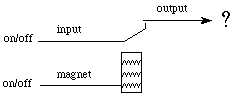
Logic through switching
If we use the common symbol 0 for "off" and 1 for "on" note that the output tables below correspond to the two different types of relay switches discussed above.
            Normally open          Normally closed

                Input                  Input
               0     1                0     1
            -----------     	      -----------
control 0   |  0     0        	0   |  0     1
control 1   |  0     1        	1   |  0     0
If we allow the "off" and "on" switches to represent the logic values "false" and "true" then it
is also possible to use these simple switches to build LOGIC CIRCUITS.
            Normally open          Normally closed

                Input                  Input
               F     T                F     T
            -----------     	      -----------
control F   |  F     F        	F   |  F     T
control t   |  F     T        	T   |  F     F
Before we go further with logic circuits, let's get familiar with using notation of FORMAL LOGIC
A "logic table" or "truth table" is constructed by considering all of the possible states that the logic variables could have. For a logic problem with n-variables there will be 2n rows in the logic table. For example, a simple two-variable problem will have 4 rows:PQ (also P.Q) means P AND Q -- true only when both P and Q are true
P+Q means P OR Q -- true is long as either or both P and Q are true
P' means NOT P -- the opposite of PBoolean function – has one or more input variables and yields a result that depends only on the values of these variables. For example: f(A) = 0 when A = 1 and f(A) = 1 when A = 0 ( NOT function )
Other notations: 1110 means NAND, 0001 means AND, & 0111 means OR
   P   Q
  --- ---
   T   T
   T   F
   F   T
   F   F
while a three-variable problem will have 8 rows:
   P   Q   R
  --- --- ---
   T   T   T
   T   F   T
   F   T   T
   F   F   T
   T   T   F
   T   F   F
   F   T   F
   F   F   F
Note that even with a simple two-variable problem, there are MANY possible outcomes of the logical combinations. In fact, there are 22n possible output states:
                Possible outputs

   P   Q    |   1   2   3   4   5   6   7   8   9  10  11  12  13  14  15  16
  --- ---   |  ---------------------------------------------------------------
   T   T    |   T   T   T   T   F   T   T   F   T   F   F   T   F   F   F   F
   T   F    |   T   T   T   F   T   T   F   T   F   T   F   F   T   F   F   F
   F   T    |   T   T   F   T   T   F   T   T   F   F   T   F   F   T   F   F
   F   F    |   T   F   T   T   T   F   F   F   T   T   T   F   F   F   T   F
Note that with 2 input variables (4 input states), we have 24=16 possible output combinations. With 3 inputs to
our logic equation there are 256 possible output combinations. With only 4 inputs, there are 65,536
possible output combinations and with 8 inputs there are more than 1077 possible combinations! (Extra credit -- write them all out... only kidding)
With a two-valued logic problem, we have names for the various output combinations. For example, the 2nd output column above corresponds to the logical operation called OR (true as long as one or both of the variables are true); the 12th column is the logical operation AND (true only when both of the variables are true). Some of these outputs are less familiar. For example, the 5th column is called NAND (false only when both inputs are true); the 8th column is called XOR (true when one but not both of the inputs are true).
ANY OF THE POSSIBLE OUTPUT COMBINATIONS can be produced by combining AND, OR and NOT operations. (In fact, they can be produced by using just the NAND gate - more on this later.) These boolean functions can be described by giving a "sum" (OR) of at most 2n n-variable "product" (AND) terms. What does this mean? A boolean function can be represented by an equation -
M=A'BC+AB'C+ABC'+ABC. This function can also be represented with a truth table:
| M=A'BC+AB'C+ABC'+ABC. Steps to produce the equation:
|
Note that this works for 3-valued, 4-valued, or n-valued logic systems; it may not be elegant but it's general!
Example
How can we construct the XOR outcome using a combination of AND, OR and NOT?
Solution
a. The XOR table look like this:
   P   Q    |   P XOR Q
  --- ---   |  ---------
   T   T    |      F
   T   F    |      T      <--- this row is needed
   F   T    |      T      <--- this row is needed
   F   F    |      F
Note that there are two rows with True as their result. The row with P = True, Q = False and the row with P = False, Q = True.
b. First result: P = True, Q = False.
What combination of these P, Q values would lead to True?
PQ = False
PQ' = True
P'Q = False
P'Q' = False
Second result: P = False, Q = True.
What combination of these P, Q values would lead to True?
PQ = False
PQ' = False
P'Q = True
P'Q' = False
Thus we find that the first result comes from PQ' while the second result comes from P'Q.
c. Combining the results in b we have, XOR(P,Q) = PQ' + P'Q
Boolean Circuit Equivalence
Just like in regular algebra - we can simply a function so that we can reduce the number of gates and lower the cost. To do this, we use boolean algebra: AB + AC is equivalent to A(B+C).
Theorem
P+Q = (P'Q')'Proof by logic tables
a. Construct the logic table for P, Q, and P+Q.
b. Construct the logic table for P, Q, (P'Q')'
c. Demonstrate the the outputs are exactly the same.
By inspection of the columns P + Q and (P'Q')' we see that these are equivalent.P Q | P + Q --- --- | ------- T T | T T F | T F T | T F F | F P Q | P' Q' P'Q' (P'Q')' --- --- | ---- ---- ------ ------- T T | F F F T T F | F T F T F T | T F F T F F | T T T F
In this way, we can redraw the earlier diagram for the OR-gate as:


Using these laws, we can arrive at the same conclusion as above: P+Q = (P'Q')'
1. First let's consider what happens
to a value that is negated and then negated again - P'' = P.
Note: In the truth table below the value for P is the same as
the value for P'' therefore P = P''
| ||||||||||||
2. Using DeMorgan's Law (A+B)' = A'B' ...if we negate both sides - (A+B)'' = (A'B')' and we remember that P'' = P then we get (A+B) = (A'B')'
Using Gates To Create A Boolean Function
How do we build circuit to perform a certain function? Let's consider the XOR function -
XOR(P,Q) = PQ' + P'Q
Steps
1. Write down the truth table for the function
2. Provide inverters to generate the complement of each input
3. Draw an AND gate for each term with a 1 in the result column
4. Wire the AND gates to the appropriate inputs
5. Feed the output of all AND gates into an OR gate
So for this example, We need, P, Q, P' and Q', and then we'll assemble
them with AND gates. For example, PQ' is
which can be written in "shorthand" as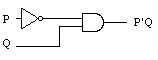
which, when combined with a similar set of components for PQ' and an OR gate leads to the final solution,
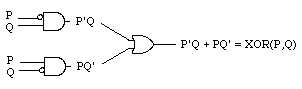
Note that this circuit requires 8 transistors.
Use the Boolean Laws to create a circuit that does the same function but uses different kinds of gates:
Homework
1. Consider the circuit:
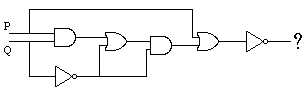
a. How many transistors would be required to build this circuit?2. Using logic tables, prove that (PQ)' = P' + Q'b. What is the logic statement which corresponds directly to this circuit?
c. Write the the logic table (truth table) for this circuit.
d. Draw an "equivalent" circuit which is simpler (i.e. the circuit must have the same
outputs for the same inputs using fewer gates).
3. The NAND gate is an AND gate with an inverter connected to its output; that is, if the inputs are
called P and Q, then the output is (PQ)'. NAND gates are usually written in circuit drawings as:
Write the logic table for the
NAND gate.
4. The NAND gate is a "universal" gate in that all other
gates can be built from this gate.
a. If one input of a5. Textbook homework problems, page 308: 2,3,4,5,6.NANDgate is connected directly to power (always 1) and the other
input is connected to a wire representing the value of P, what is the output? What is this
gate called?b. Show how two
NANDgates can be connected together so that inputs P and Q will
result in the output PQ.c. Show how three
NANgates can be connected together so that the inputs P and Q will
result in the output P+Q. Hint: remember from lecture that P+Q = (P'Q')'